


Please Leave Us A Message
Privacy statement: Your privacy is very important to Us. Our company promises not to disclose your personal information to any external company with out your explicit permission.

 October 17, 2022
1. Rectifier and filter circuit
The task of the rectifier circuit is to use the unidirectional conductivity of the diode to convert the positive and negative alternating 50Hz grid voltage into a unidirectional pulsating DC voltage.

The rectifier circuit only converts AC power into unidirectional pulsating voltage and current. Because the latter contains a large AC component, it is usually necessary to connect a filter circuit at the output of the rectifier circuit to filter out the AC component and obtain a smooth DC Voltage.
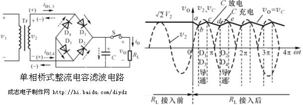
It can be seen from the waveform:
1. When the switch S is opened, the voltage across the capacitor is the maximum value of the transformer secondary side  .
.
2. The switch S is closed, that is, the capacitor filter resistance load, when the voltage on the secondary side of the transformer is greater than the voltage on the capacitor  , The capacitor is charged, the output voltage rises, when
  When the capacitor discharges, the output drops. Such fast charging and slow discharging are repeated continuously, and a relatively smooth output voltage will be obtained on the load. When the load resistance is larger, the discharge is slower, the ripple voltage is smaller, and the load resistance is small, the discharge is fast, the ripple is large, and the output voltage is low.
To this end, there are three estimated output voltages:
1) Capacitor filtering, when the load is open  .
.
2) When there is no capacitor filter and resistive load, the average output voltage is:  .
.

3) Capacitor filtering, resistance load is usually estimated with the following formula 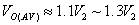 , Usually by
  Estimate.
In order to ensure the safe operation of the diode, it is required that different electronic devices require different levels of smoothing of the power supply voltage. For this reason, different filter circuits can be used. Common ones are capacitive filtering, inductive filtering and compound filtering circuits (composed of two or more filtering components).

2. Linear series voltage regulator circuit
The voltage after rectification and filtering is unregulated. When the grid voltage or load changes, the voltage will change, and the ripple voltage is large. Therefore, after rectification and filtering, it must go through a voltage regulator circuit to make the output voltage stable within a certain range.
1. Main performance indicators of voltage stabilizing circuit (power supply)
Output stable voltage value Vo, maximum output current Imax, output ripple voltage V~, voltage regulation coefficient (voltage adjustment rate)  ,
, 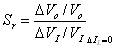 The smaller the value, the better the stability
  .
.
Output resistance (internal resistance)  ,
,  , The smaller the internal resistance, the better.
2. The basic idea of the basic structure of the series voltage stabilizer circuit:
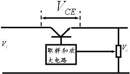

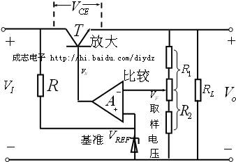
Series type:

When the input voltage (VI) changes, it can automatically adjust the size of the (VCE) voltage to keep the output voltage (Vo) constant. For example: VI↑→Vo↑→After sampling and amplifying circuit→IB↓→VCE↑→Vo↓
Basic structure of series voltage stabilizing circuit:

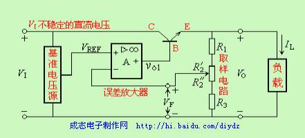
VI is the voltage after rectification and filtering, T is the regulator tube, A is the comparison amplifier circuit, and VREF is the reference voltage, which is composed of the regulator tube Dz and the current limiting resistor R. R1 and R2 form a feedback network, which is a sampling link used to reflect changes in output voltage.
The circuit can also be redrawn into the following form for easy viewing.
If the series regulator circuit is regarded as a feedback amplifier (input is VI, output is Vo), then this kind of circuit belongs to voltage series negative feedback.
Under deep negative feedback conditions 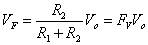 ,
,  ,
,  .
.
The main loop of this voltage stabilizing circuit is composed of a regulator tube T in series with the load, and T works in a linear state, so it is called a linear series voltage stabilizing circuit.
The output voltage Vo=VI-VCE, its variation is sampled by the feedback network, and amplified by the amplifier circuit (A) to control the base voltage of the regulator T, thereby changing the VCE of the regulator T. When the input voltage VI increases (or the load current Io decreases), the output voltage Vo increases, and the feedback voltage VF=R2Vo/(R1+R2)=FvVo also increases (Fv is the feedback coefficient). VF is compared with the reference voltage VREF, and the difference voltage is amplified by the comparison amplifier circuit to reduce the VB and IC of the regulator tube, so the voltage VCE between the regulator tube T increases, so that Vo decreases, thereby maintaining Vo basically constant. Obviously, this is the basic performance of the voltage negative feedback circuit.
The above is the Knowledge sharing of rectifier and filter circuit and linear series voltage stabilizer circuit we have listed for you. You can submit the following form to obtain more industry information we provide for you.
You can visit our website or contact us, and we will provide the latest consultation and solutions
Send Inquiry
Most Popular
lastest New
Send Inquiry
Privacy statement: Your privacy is very important to Us. Our company promises not to disclose your personal information to any external company with out your explicit permission.
Fill in more information so that we can get in touch with you faster
Privacy statement: Your privacy is very important to Us. Our company promises not to disclose your personal information to any external company with out your explicit permission.