


Please Leave Us A Message
Privacy statement: Your privacy is very important to Us. Our company promises not to disclose your personal information to any external company with out your explicit permission.

 October 18, 2022
Generally speaking, the input capacitor of the 3.3V voltage regulator chip is for filtering, and the capacitor is added at the output to prevent oscillation and degradation of voltage regulation performance. But this is really not so absolute. Now the chip design is getting better and better and the craftsmanship is getting better and better. Some chips can work even without adding capacitors, and you won't find the problem immediately. This is an experiment I have done. However, considering the practical application, it is better to add a capacitor, insurance! There are already chips connected to 1uF capacitors that can work stably, and they do not occupy a lot of circuit board area.
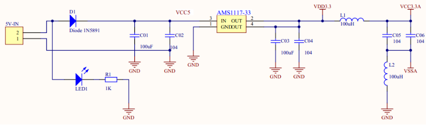
Typical circuit diagram and analysis of 3.3v voltage regulator circuitThe following figure is a typical schematic diagram of ASM1117-3.3V. Since I chose a four-pin schematic, here is a typical circuit of the four-pin schematic:
When I was drawing the circuit diagram of the SD card module today, I found that the working voltage of the SD card is 3.3V, so it is necessary to use a voltage regulator chip to convert the 5V power supply into a 3.3V voltage, so I just found a little information about the voltage regulator chip.
The voltage regulator chip we chose is ASM1117-3.3, and the package is SOT-223
However, we encountered some problems when drawing the schematic diagram. We found two schematic diagrams of the ASM1117-3.3V chip in the schematic library, which are:
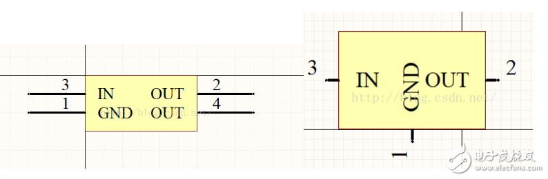
The first one is four-pin, the second one is three-pin, but after checking the package, the package of both schematic diagrams is SOT-223, but the package of SOT-223 is four-pin. The problem that bothers me is why The three-pin schematic can correspond to the four-pin package. Later, I read the chip manual to solve this doubt. The original 2 pins and 4 pins of the chip are connected, so it does not matter even if the three-pin schematic corresponds to the four-pin package
When drawing this circuit, we also encountered a problem. The components of the inductance between the network labels VDD3.3 and VCC3.3 have not been determined at the beginning, because we have searched a lot of ASM1117-3.3 circuits. There are inductors and resistors. After reading the chip manual carefully and asking teachers with relevant knowledge, I know whether the components in this position can be connected or not, which will not have much impact on the circuit.
The following is an analysis of the circuit:
1. The function of D1 is to prevent reverse connection of the power supply.
2. C01 and C02 are power input filtering.
3. VDD3.3 is a 3.3V power supply for digital circuits.
4. L1 and L2 are isolation filter inductors.
5. VCC3.3 is a 3.3V power supply for analog circuits.
The advantage of dividing the voltage regulator chip into a module is that all peripherals can be directly connected through the network label when level conversion is required, without the need to draw the circuit again, which can save drawing time and save The cost of components.
In addition to the 3.3V voltage regulator chip, the 2.5V voltage regulator chip is also used in this project. The circuit connections are very similar, so I won't repeat it.
The above is the 3.3v voltage stabilizer circuit capacitance function 3.3v voltage stabilizer circuit typical circuit diagram and analysis we have listed for you. You can submit the following form to obtain more industry information we provide for you.
You can visit our website or contact us, and we will provide the latest consultation and solutions
Send Inquiry
Most Popular
lastest New
Send Inquiry
Privacy statement: Your privacy is very important to Us. Our company promises not to disclose your personal information to any external company with out your explicit permission.
Fill in more information so that we can get in touch with you faster
Privacy statement: Your privacy is very important to Us. Our company promises not to disclose your personal information to any external company with out your explicit permission.